- English
- Español
- Português
- русский
- Français
- 日本語
- Deutsch
- tiếng Việt
- Italiano
- Nederlands
- ภาษาไทย
- Polski
- 한국어
- Svenska
- magyar
- Malay
- বাংলা ভাষার
- Dansk
- Suomi
- हिन्दी
- Pilipino
- Türkçe
- Gaeilge
- العربية
- Indonesia
- Norsk
- تمل
- český
- ελληνικά
- український
- Javanese
- فارسی
- தமிழ்
- తెలుగు
- नेपाली
- Burmese
- български
- ລາວ
- Latine
- Қазақша
- Euskal
- Azərbaycan
- Slovenský jazyk
- Македонски
- Lietuvos
- Eesti Keel
- Română
- Slovenski
- मराठी
- Srpski језик

Aluminum die casting design guide
Aluminum Die Casting Design Guide: Optimizing for Performance and Production
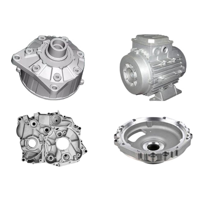
This aluminum die casting design guide provides essential principles for creating high-quality, manufacturable, and cost-effective aluminum alloy components. Aluminum casting is a highly efficient process for producing complex, high-volume metal parts with excellent dimensional accuracy and smooth surface finishes. By following proven design strategies, you can avoid common pitfalls and leverage the full potential of die casting. For foundational knowledge, our resource on Aluminum casting explains the core process. To delve deeper into practical application, explore our aluminum casting tips for expert recommendations on material selection and tolerances. Whether you are a seasoned engineer or a hobbyist starting with an aluminum casting kit, understanding design fundamentals is crucial for success.
Effective design for <产品名字> begins with strategic planning around key parameters. Wall thickness uniformity is paramount; maintaining consistent thickness promotes even metal flow, solidification, and reduces defects like warping or porosity. Generous fillets and radii at corners and intersections improve structural integrity and enhance metal flow. Draft angles are non-negotiable for part ejection; a minimum of 1 to 3 degrees per side is standard, depending on the surface depth and texture. Ribs and bosses should be used to add strength without increasing wall thickness, but their design must follow specific ratios relative to the nominal wall. Properly designed gating and overflow systems are critical for directing molten metal into the die cavity while venting air and gases. Below are key material and process specifications for a typical aluminum die casting project:
Common Aluminum Alloys for Die Casting:
- A380: Excellent fluidity, good mechanical properties, and corrosion resistance. Most widely used.
- A383 (ADC12): Good dimensional stability and resistance to hot cracking.
- A360: Superior corrosion resistance and pressure tightness.
- A413 (ADC6): Excellent pressure tightness and ductility.
| Design Parameter | Recommended Value / Guideline | Purpose & Benefit |
|---|---|---|
| Nominal Wall Thickness | 0.9 mm - 4.0 mm (0.035" - 0.157") | Ensures proper fill and solidification; minimizes weight and cost. |
| Draft Angle (External/Internal) | 1°-2° / 2°-3° per side (minimum) | Facilitates part ejection, prevents drag marks and die damage. |
| Fillet Radius (Corners) | Minimum 0.5 mm (0.020"); ideally equal to wall thickness | Reduces stress concentration, improves strength and metal flow. |
| Rib Thickness | 50% - 80% of adjacent wall thickness | Adds stiffness without creating sink marks or porosity. |
| Boss Base Radius | Minimum 0.25 mm (0.010") | Prevents cracking at the base during cooling and service. |
| Parting Line Tolerance | ±0.1 mm to ±0.25 mm (±0.004" to ±0.010") | Defines achievable dimensional accuracy across the die parting. |
| Surface Finish (As-Cast) | 1.6 - 6.3 μm (63 - 250 μin) Ra | Standard finish from die surfaces; can be improved with polishing. |
Designing for manufacturability also involves considering secondary operations. Identify areas for potential machining, such as threads, precise bores, or sealing surfaces, and provide adequate stock material. Strategically place ejector pin marks on non-cosmetic surfaces. Incorporate logos and part numbers as raised or recessed features directly into the die design to avoid additional processing. Minimizing undercuts is essential for a simple, cost-effective die; if necessary, discuss sliding core options with your die caster early in the design phase. By integrating these parameters and guidelines from the initial concept, you ensure your <产品名字> is optimized for both superior performance and streamlined, economical production.
Related Products


Hot Products

Brass CNC Machining
Brass is one of the easiest metals to machine, with many years of experience and proven expertise, our brass machining capabilities enable us to deliver high precision parts and components that match your design specifications. We utilize advanced Youlin® Brass CNC Machining technology to ensure perfect precision and repeatability, whether you need a handful of prototypes or full production runs with quantities in the tens of thousands. No matter how simple or complex your design may be, we will give you the flawless brass parts your project requires.
Stainless Steel Forging
Youlin stands ready to be your forging partner. We forge parts in a variety of stainless steel alloys. Whether you need simple open die forged parts or seamless rolled rings, Youlin will ensure your Youlin® stainless steel forging parts will meet your needs. Our expert team of engineers, metallurgists, and quality personnel guarantee our forged parts meet various quality standards.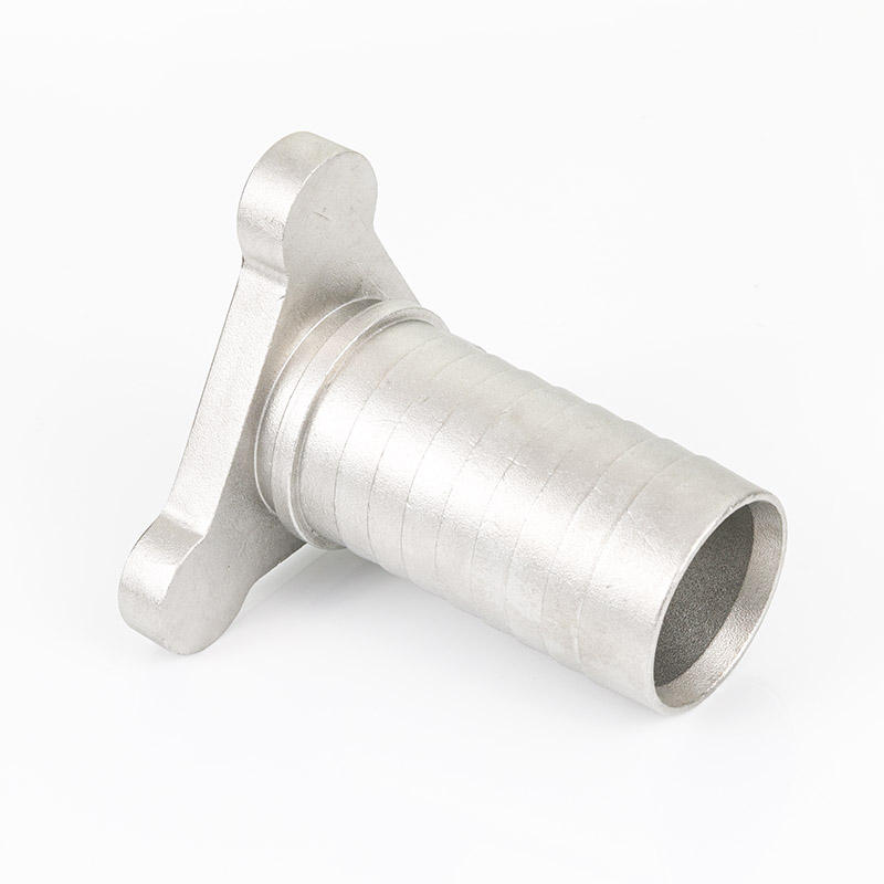
High Precision Metal Turing Machining Parts
China Youlin® High Precision Metal Turing Machining Parts Suppliers. Youlin is a leading provider of high integrity CNC Lathe Machining services to a diverse mix of demanding industries. With an energetic staff of technically astute manufacturing professionals, we have the ability to handle jobs of any size or geometric complexity while meeting firm delivery commitments.
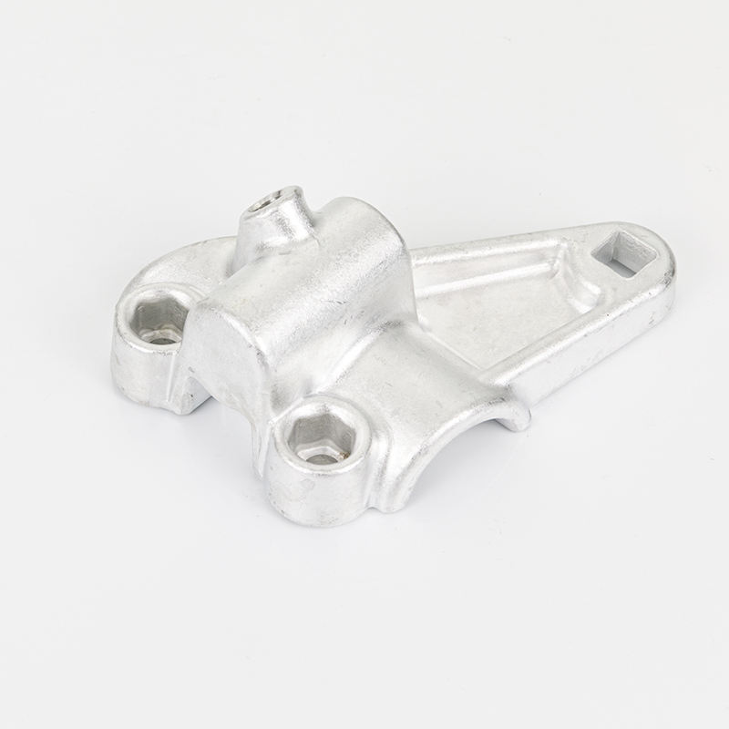
Precision Aluminum Forging Parts
Ningbo Youlin Trading Co., Ltd. is a professional manufacturer and supplier of precision aluminum forging parts in China. We specialize in forged aluminum 6061-T6 components with die casting, forging & CNC machining, tight tolerance ±0.05mm, and customized services. Widely used in motorcycles, plumbing fittings, automotive, industrial, and other fields. Certified with ISO9001, ISO14001, IATF/TS16949, and RoHS. We provide OEM/ODM solutions and welcome long-term cooperation.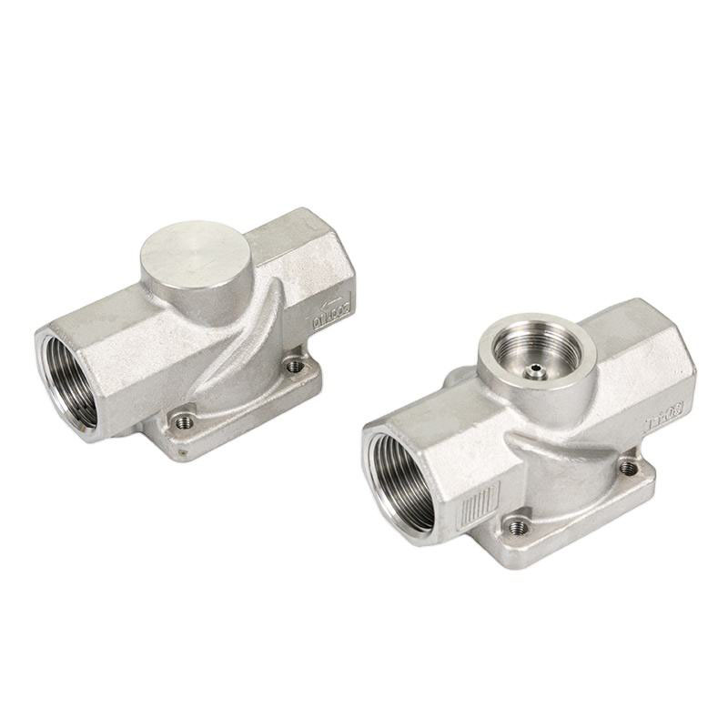
Casting Pneumatic Valve Body
Ningbo Youlin Trading Co., Ltd. is a large-scale Casting Pneumatic Valve Body manufacturer and supplier in China. We have been specialized in Customized CNC Machining Services of any complexity for the production of Casting Pneumatic Valve Body for many years. Our products have a good price advantage and cover most of the European and American markets. We look forward to becoming your long-term partner in China.
Carbon Steel Sheet Metal Stamping Part
Ningbo Youlin Trading Co., Ltd. is a large-scale Carbon Steel Sheet Metal Stamping Part manufacturer and supplier in China. Customized OEM Youlin® Carbon Steel Sheet Metal Stamping Part Manufacturers. Youlin excels in supplying only the finest quality made metal forging components for your application, at ultra-competitive prices. Our highly qualified technical team will find a way to reduce your costs by 20% or more, with the added convenience of a one-stop-shop for all your metal part needs. We specialize in high-volume production runs, with short lead times and fixed order pricing.
- Related Blog
- Reviews